UxV/35™ Test Boards
Test the boards and their configurations at the bench or in the field.
KA1051-01 UxV/35™ Test Boards Set
The availability of UxV/35™ test boards makes it very easy to adapt, integrate and validate UxV/35™ systems at the bench or in the field.
These test boards address the common needs such as voltage verification, communications existence, etc.
This set puts together the essentials for testing and deploying a UxV/35™ stack. It includes the following boards:
- KA1031-01 Serial Test
- KA1033-01 Serial Loopback
- KA1034-01 Stack Voltage
- KA1035-01 LED Status
- KA1036-01 Digital Input
- KA1039-01 Multi-Source Test Power
See below for more details about these boards and links to their datasheets.
KA1031-01 Serial Test
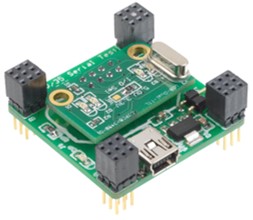
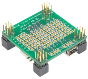
This UxV/35™ test boad brings out all the assigned serial channels present on the UxV/35™ stack and presents them to a dual port USB-to-serial converter.
Any of the six (6) UxV/35™ serial ports can be assigned to either of the two (2) USB serial ports. There is null modem capability on each channel to eliminate any Tx/Rx mismatch.
The board is powered by the USB port and can power the UxV/35™ stack up to the power limits of the USB host.
This board is great for usage as a MAVLink interface or to access and test the serial stream from a GPS or other serial device on the UxV/35™ stack.
KA1033-01 Serial Loopback
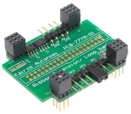
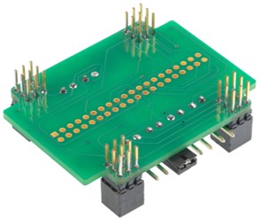
The UxV/35™ standard has six NRZ serial streams, often referred to as TTL serial. The easiest way to test these is by the addition of a loopback on the desired serial Tx/Rx pair.
This board provides jumpers for each of the serial pairs that shorts the Tx to the Rx so that a transmitted signal on the Tx can be read on the Rx.
Additionally, there are two I2C memories that can be read on the two I2C busses present on the UxV/35™ stack.
A ribbon cable connection footprint is provided, that when loaded, allows the full UxV/35™ stack to be connected elsewhere.
KA1034-01 Stack Voltage
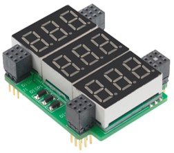
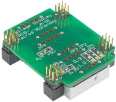
This test board measures and displays the three primary voltages present on the UxV/35™ stack. This includes Vin, +5V and +3.3V.
The board is self-powered by the stack and displays the actual voltage read from each.
It can be configured so that it can read the RSSI (Radio Signal Strength Indicator) on the 5V display and amps in (Current usage) on the 3.3V display.
KA1035-01 LED Status
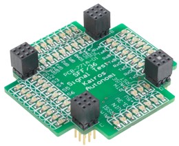
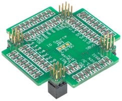
Each of the signals on the UxV/35™ stack
can be read with a status LED on this board.
Each signal is read with a red and green LED. Signals driven high, driven low, or open can be read.
All signals are clearly labeled and broken into UxV/35™ groups.
Each type of operation can be seen in patterns presented in the LED. Activity on serial lines, enabling of servo signals, status of digital lines, etc. can be observed.
KA1036-01 Digital Input
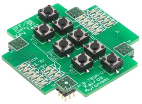
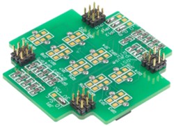
Some of the signals on the UxV/35™ are status and commands to classes of boards such as the defined stack safety signals.
This board can be configured to activate each of the available safety signals as well as the general-purpose signals.
KA1039-01 Multi-Source Test Power
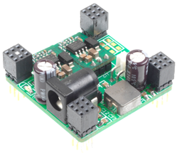
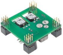
The UxV/35™ stack has three primary voltages – Vin (7-20V), +5V and +3.3V.
This test board uses an external source to create 3.3V and 5V while routing that external voltage source up the bus.
This is used for powering a UxV/35™ stack from a test bench source to stack testing and deployment.